|
|||||||||||||
|
|


The Grand Canyon Current Landscape A typical design requires the modeling of 25-50 analog blocks on average. Each block requires a model and a testbench. The average model contains 250 lines, and testbenches typically contain upward of 1000 lines. Thus, a design can require writing 25,000-50,000 lines of code. That’s a lot. Much of the code tends to be repetitive and tedious and time-consuming to write. The repetitive nature of the code causes many to write scripts to accelerate the model creation. That helps, but this is a difficult vein to mine. Without a huge effort, the gains are limited, and the process remains problematic. In light of these numbers, verification engineers almost universally focus only on writing models and attempt to reuse testbenches created by designers to verify their models. Designer created testbenches generally focus on verifying the performance of the block and are not well suited to functional verification, leaving the models woefully untested. Furthermore, it is extremely difficult to automate testing with the schematic-based testbenches favored by designers. The result is that the models created by the verification engineers remain largely unvalidated. Finally, there is no common language between the design and verification engineers. Verification engineers struggle to read schematics and so can find it difficult to know what is to be modeled, and design engineers struggle to read models and so find it difficult to know what was modeled and whether it was modeled correctly. Without comprehensive self-checking testbenches, the feedback loop between the two is broken, allowing errors to be missed. Models in Minutes
Ken and Henry have spent years thinking about what’s needed in an analog verification tool suite. MiM provided everything we needed from model and testbench generation to managing thousands of models.
Lead verification engineer for a power management group
Our product, Models in Minutes or MiM, changes this game. It automates the process of writing both the model and a fully self-checking testbench. MiM starts from a simple functional specification of the block. A typical specification is given with the equivalent of about 25 lines of code. Thus MiM converts the challenge of writing the 25,000 lines of code needed to verify the analog portion of the design to writing less than 1000. MiM also generates collateral to automate the management of the model. With this collateral, you can run the simulation that fully validates a model by typing a single line. Another benefit of this approach is that the specification is a common language that is understood by both the designer and the verifier. Either can create the spec. When designers create the spec, they are communicating to the verifiers what is to be modeled. Verifiers can then complete the spec and run MiM. When the verifiers create the spec, they are communicating to the designers what has been modeled. The designer can then edit the spec to correct any errors. It is common for designers to write informal specifications for their designs. What is new is that MiM formalizes that spec, making it machine-readable. It then uses the spec to generate the model, testbench, and verification collateral. In this way, the spec becomes executable, which leads to it always being current and complete. And since the spec generates the model and testbench, and the testbench assures that the model matches the schematic, MiM assures that the spec, the model, and the schematic are all consistent with each other.
Creating and Validating a Model
This is the first modeling tool that takes a pin based approach. It’s the most efficient way that I’ve seen for describing functionality.
Verification lead for mixed-signal chips
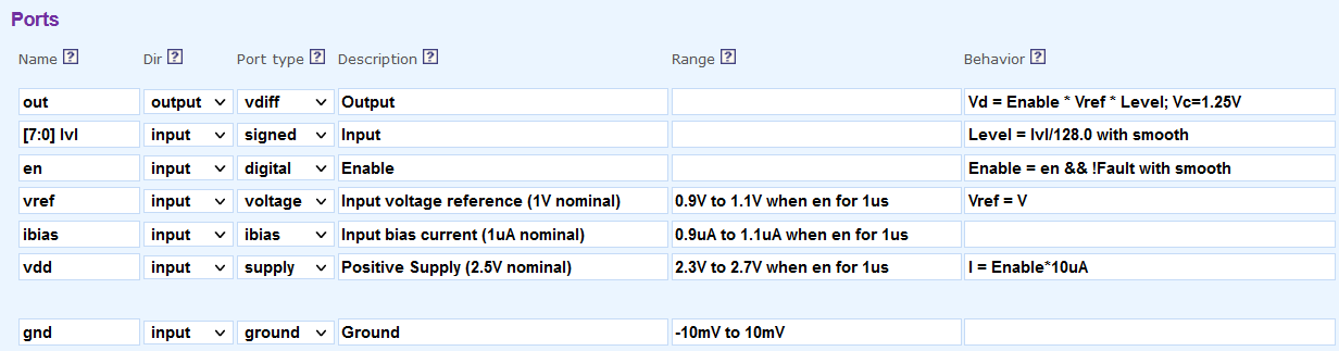
To demonstrate the use of MiM, a digital-to-analog converter (DAC) is modeled and verified. The DAC is expected to produce a value between 0 V and 1 V depending on the digital input value. Each increment in the input value increments the output by 4 mV. First, a spec would be created on the MiM website that describes the block.
While some additional information is required, the block is largely described below:
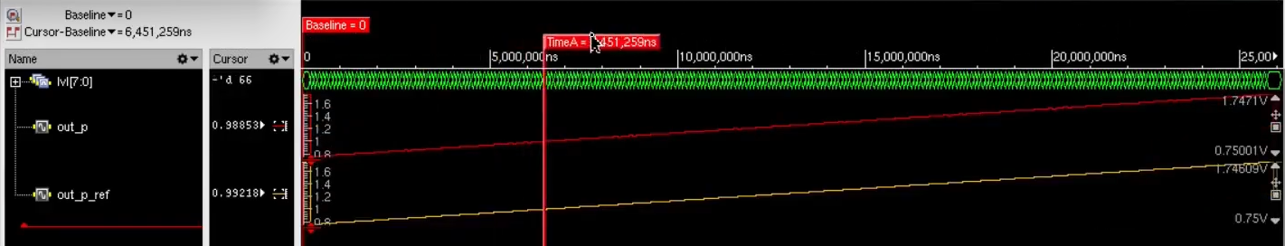
Notice that this spec is easily created and understood by both the verification and design engineers. Now, if you press the Generate & View button you will be taken to a page that contains the generated model. Also, at the top, you will see the line: Now, open a shell, create a working directory for this block, and download the files. Notice that you have downloaded the model (Local/DGC.dac:MiM.vams), the testbench (Local/DGC.dac_tb:MiM.vams) as well as various collateral files, such as connect modules, configurations, the specifications in JSON format, and the specifications as a PDF file, and the AV settings file. AV is a program provided by us that you use to manage your verification. Here it was used to download all the files associated with the block. DGC is the library name, and dac is the cell name. At this point, the testbench is just a shell because we did not add any information to the spec sheet on how to test the block. However, you can publish the model to your Cadence® design hierarchy and run it with any existing testbench you might have. Now information on how the model should be tested is added to the spec sheet. The testing is done by simulating both the schematic and the model together while applying the same stimulus to both and observing and comparing their outputs. The test fails if the outputs differ by a significant amount.
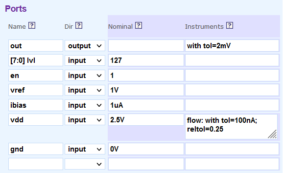
Two additional columns are needed for the testbench, the Nominal column and the Instruments column.
In less than 45 minutes, Ken demonstrated how to generate a model and testbench, and verify that the generated model and schematic were functionally equivalent.
Design manager of a power management group
The Nominal column specifies the nominal value of input pins. The nominal value is the value driven on to the port when that port is not being exercised by a particular test. By default, all digital input pins are exercised by sweeping through all their values while tests (comparisons) are performed for each value. Thus, the adjust signal steps through all 64 values while it is being exercised, and sits at its nominal value of 0 while the other ports are exercised. The instruments column specifies how to observe the various outputs. By default, all outputs are observed, but we have also specified that the current on the supply pin be observed. In this case, the observations are simply the settled values of voltages and currents at the end of the test interval, but more sophisticated observations are possible. Once you save the updated spec sheet, you can shift back to your shell to run simulations to compare the model against the schematic.
At this point, you can make updates to your model and re-simulate. Notice that the publish and populate steps are not needed as long as only the model and testbench change. This avoids the long netlisting step (populate), which can dramatically speed up your edit/simulate loop on small blocks. Once you are satisfied with your model, you can publish them to the design hierarchy. You now have a fully validated model in your design hierarchy that you can share with the team. Examples
Reviewing the Model
As a modeling engineer, I often don’t know what the schematics do, especially all of the control bits. Within minutes using MiM, I can use the testbench generator to launch a simulation and simulate a block through all its modes and settings to see what the block does.
New verification engineer on a verification team
Once a model has been created and published, designers may easily review and edit the model by way of the spec. The designer simply opens the block’s spec view in the Cadence® Hierarchy Editor. This is a convenient way for the designer to check the work of the verifier. It is much easier than reading the model itself or wading through the waveform results from hundreds or thousands of individual tests. If any errors are found, the designer may login and edit the spec directly. Managing all of Your Models and Automating Block-Level Verification MiM aids with keeping all of your models up-to-date. Schematics change sometimes all the way up until tape out. With MiM you can easily update your models, verify them, and then rerun top-level tests to assure that no errors are introduced with last minute changes. The pressure is always on, and with deadlines looming, it is important track your progress. MiM assists with that as well.
Chip-Level Verification
I was surprised by how fast our chip-level simulations ran with Verilog-AMS. We were able to run 2 minutes of chip time in a 45 minute simulation. Because of this, I determined that some of our embedded software default settings were not optimal.
Lead architect for a power management chip
MiM is not just about creating and validating block level models. It’s also helps to efficiently manage the tens to hundreds of models that are required for chip-level verification.
Key Features of Models in Minutes Version 2 (MiM-2)
Key New Features in Both Versions of MiM
Getting Started There are several ways to get started.
*All trademarks are the property of their respective owners. |
|||||||||||||||||||||||||||||||||||||||||||||||||||||||||||
|
|
|||||||||||||||||||||||||||||||||||||||||||||||||||||||||||